|
|
Detector Bias, Control, and SQUID Electronics
The photograph to the right shows the 66-channel SQUID system and detector bias and control electronics for CRESST II before it left Oxford in March 2004. On the left,
the wooden structure holds in place the components are now fitted into the cryostat in LNGS. Near the floor, the 66 SQUID sensors are shown mounted
on the flange which represents the bottom of the helium main bath in the cryostat. Above the cryostat top plate (held by horizontal battens) are the
electrical connector boxes for 864 wires and the front-end amplifiers (black box) for the SQUID system. The SQUID control electronics in the lower
third of the rack (on the right) is complete; the detector bias and control
modules (shown below) fit into the empty sub-frame in the middle part of that rack.
The electronics modules to produce the detector bias currents, and
the heater currents used to stabilise the detectors were designed and
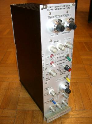
built in Oxford. The photographs below show the old and new electronics.
The new modules require a factor 5 less volume, and allow users to control all parameters remotely
(from outside the Faraday cage), but also ensure that there is no
digital noise when the detectors are running.
|
|
|
|
The old (left) and new (right) heater-bias electronics.
The new modules supply the bias and stabilization currents to two
detectors, and are significantly smaller than the old single channel
units. |
|

|
| The 66-channel readout system for CRESST II, photographed in Oxford before it was shipped to Gran Sasso. |
|
|
|
|
| |
physics, oxford, university, the university of oxford, conference, conferencing, admissions, undergraduates, jobs, astrophysics, condensed, matter, atmospheric, laser, atomic, particle, theory, theoretical, ocean, planet
|
|


